


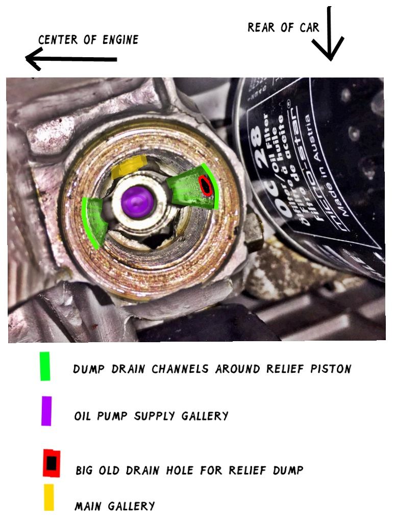
1. Oil Pressure Relief Valve - located at left rear of engine
2. Oil Control Valve - located at front left of Type 1 engine
(Type 4 is located between #1 lifter bores)
Lubrication of our engines depends on a supply of pressurized oil through galleries drilled in the case and the crankshaft to the main, rod, and cam bearings, and via the lifters to hollow pushrods to the rocker arm bushings and valve adjustment screws. Downstream components like cam lobes, gears, flywheel shims, pistons, cylinder walls, and distributor bushings, get their lubrication from spray coming off the main and connecting rod bearings.
1 ) Volume
The quantity of oil brought to a specific number of rotating journals/bearings required to maintain a hydrodynamic film and rinse away heat and debris, is met by the pump's output volume. It is calculated at the drawing board and established throughout the engine by the selected diameters of both the main gallery and local supply galleries and specified bearing clearances at the recommended oil viscosity. The VW engine uses a "positive displacement" pump that moves a specific volume of oil at every rotation. It squirts roughly 2 gallons per thousand rotations. At idle (450 camshaft rpm), that is just under 1 gallon per minute to distribute through the case galleries to the following
Pressurized Lubrication Points:
* 8 lifters > pushrods > 8 rocker arm bushings/shafts > all 8 valve adjusting screws
* 3 camshaft bearing journals
** 4 main bearing journals, the front three of which also feed:
* crankshaft galleries which supply
** 4 connecting rod bearing journals
Because positive displacement pumps can crank out serious pressure without a second thought, you WILL note that oil pumps are sized for VOLUME not pressure. Required volume is dictated by the number of bearing surfaces the engine has to lubricate.
Note: system pressure ensures the delivery of required volume to the bearing. Once oil has arrived at the bearing, the working film ( about .0002" thick - less than a tenth of your bearing clearance) is maintained by a "wedge" of oil developed by rotation. This film/wedge is not dependent on system pressure, but rather the volume of oil that made it in between the journal and bearing surfaces. Think: water-skiing. The lubrication system has to fill the swimming pool, yes, but the water skier has to move to ride up on the water. (p.s. a big slalom ski board requires less water. VWs have very big boards)
2 ) Pressure
System pressure ensures the delivery of the required volumes of oil to all of the bearings. In the perfect alternate universe, pressure would be the sum total of pump volume hitting the resistances at our bearing clearances. But, pressure is more complex than that. We have to calculate the flow resistance through the galleries, all the corners, the filter media on the Type 4s, the oil cooler adapter on the horizontal Type 3 and Type 1 doghouse offset coolers, etc.
System pressure is solely determined by the engineering downstream of the selected pump volume. Don't blame the pump for the lousy oil pressure you hate, you'll lose sight of the more likely reasons for insufficient lubrication. All pressure does for us is ensure adequate supply to the far reaches of the system. Correct pressure is merely having our pump volume equitably distributed to all of our bearings at the correct flow rates. Blaming the pump right off leads you into the marketing labyrinth of tho$e who are happy to $ell you more pump capacity when your issues are very much elsewhere. If you keep passing out when you stand up, don't select the heart transplant first.
The above asteriks point to potential operating pressure deterioration over time (wholly separate from acute failures like failed gallery plugs blown up coolers, stripped out strainer plate screws, and that ol' favorite, a missing fuel pump push rod/sleeves in early Type 4 cases).
Double-asteriks denote potential serious system pressure drop caused by sloppy clearances that drain the swimming pool away on our hapless no-longer-water but more like molten-metal skier ...
Note: this is a highly engineered balancing act! Gallery diameters assist in the division of specific volumes to each bearing's supply requirement.
[ we interrupt this program for the following Type 1 Main #4 Gallery Restriction bulletin:
Since the 1960 introduction of the four main bearing crankshaft, the restrictor in the #4 main bearing oil feed is critical to maintain correct flow rate (read: not too much) to the bearing. This is the only main bearing that does not have to feed a connecting rod journal through a crankshaft drilling. Enjoy better oil pressure AND happier bearings AND less spraying out from around your pulley . . . ]
Now lets confound our highly engineered balancing act with variable temperature and rpm and of course the one-way ticket to sloppy piddling old age, wear. Galleries that are "too small" when the engine is cold, new, or at high rpm, are "too big" when the engine is hot, old, or at low rpm.
The three variables we have to chase all over the place:
a) bearing clearances (from cold to hot/new to old)
b) pump speed > volume (from idle to redline)
c) viscosity changes (from cold to hot).
aa) oil flow "X" increases exponentially through the main, rod, and camshaft bearings as clearances open up when hot, magnified as the engine ages. IF:
.002" = X @
.003" = 5X @@@@@
.006" = 25X @@@@@@@@@@@@@@@@@@@@@@@@@
bb) if we have sufficient supply at idle and when hot, we will have too much at speed and when cold. Bearings do not consume oil in as linear a fashion as pump output from idle to redline. Loose bearing clearances just gobble volume and kill pressure at high rpm.
cc) our old air-cooled engines were carefully designed with matched pump size to gallery size to bearing surface area/clearance using specified oil viscosities. The relief and control valve spring pressures, relief and control piston surface area exposure to galleries, dump port diameters, were all engineered to provide acceptable service across the full range of operating conditions.
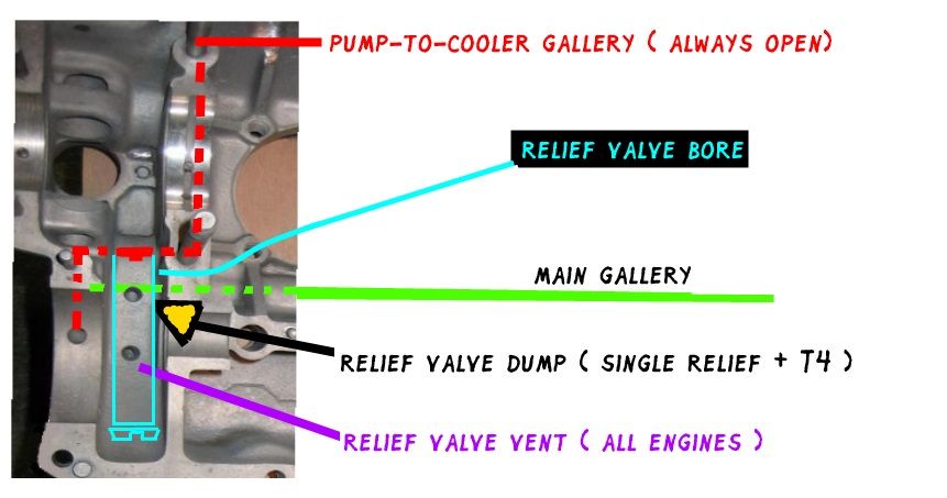
ILLUSTRATION AA - Type 1 Engines Through 1967
8mm galleries, 17/19 mm pump gears. Single relief valve with dump.
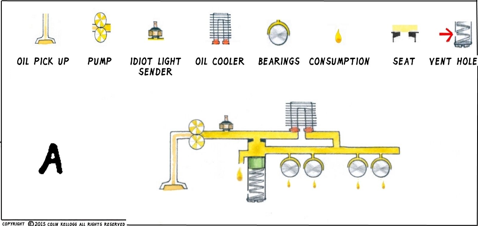
Here is a cold engine with the relief valve opened. Please note that total system pressure does act upon the cooler at all times. Note too, that cold/cool oil does not/may not flow through the cooler because of little to no pressure *differential* between the "in" and the "out" when relief valve is open. It is given the choice to do so, however, so as the engine warms up, the cooler slowly develops flow. When you expose the inlet of the cooler exclusively to the pump, and the outlet to bearing leak down, as when the relief valve closes, you will then have exclusive circulation through the cooler. According to factory specified volume/viscosity/resultant pressures, this switching occurs at a very nice 180* in the 48ish psi range.
This lubrication system just barely spanned the above listed variables but it worked acceptably for toodling around with 25/36/40 hp. As with all air-cooled engines that use alloy crankcases, hot or worn engines idle with low oil pressure. The substantial bearing surface area does not mind a barely 2 psi oil pressure . . . and VW owner's manuals state, "don't worry about a little flickering of the oil light at idle". So don't.
ILLUSTRATION B - Grooved Relief Piston 19/21 mm pump gears
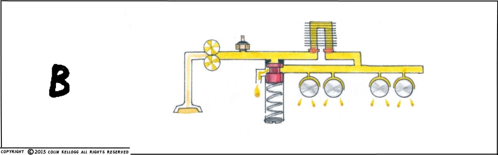
The introduction of the Type 3 1500S engine, the little 66 hp hotrod of the line-up at the time, arrived with a grooved oil relief piston. The physics of the grooved relief valve piston never was explained as to how it improves oil cooling. Subsequently, our internet universe has promulgated any number of sometimes cursory if not creative explanations. How does it actually work? How does it actually help oil cooling?
After all, the groove clearly only *works* when the valve is closed ...
This improvement gave us the first utilization of "waste circulation" whereupon the cooler is cooling off a greater quantity of oil than the bearings are consuming. When fully closed, the relief valve groove opens the main gallery to the dump port, delivering oil cooler-cooled unused oil back to the sump.
Extremely Exaggerated Example:
Old Days > Bearings consume four quarts per minute. That's four quarts sent through the cooler, then through the bearings, then those very same four quarts becomes hot oil dumping into the sump to then get picked up and sent through the cooler and back to the bearings again.
New Days > Bearings consume four quarts per minute. Grooved relief valve leaks a quart per minute. That is five quarts now going through the cooler for every four heated through the bearings. That would be a whole gallon of extra cooling every four minutes compared to the old system.
Great idea! The bad news is, this waste circulation doesn't know how to shut off in a hot engine with diminished oil pressure. Same problem as the prior designs, hot and older engines will flicker their idiot lights, the idiots.
The next improvement was a 19 mm oil pump that came along in 1967 with the new forged cross-drilled crankshaft that fed more oil to the main and connecting rod bearings. Very incremential additional flow was proferred as we owners flogged those little horses a little harder and a little faster.
ILLUSTRATION C - Type 1 Dual Relief Valves And 24mm Super Pump
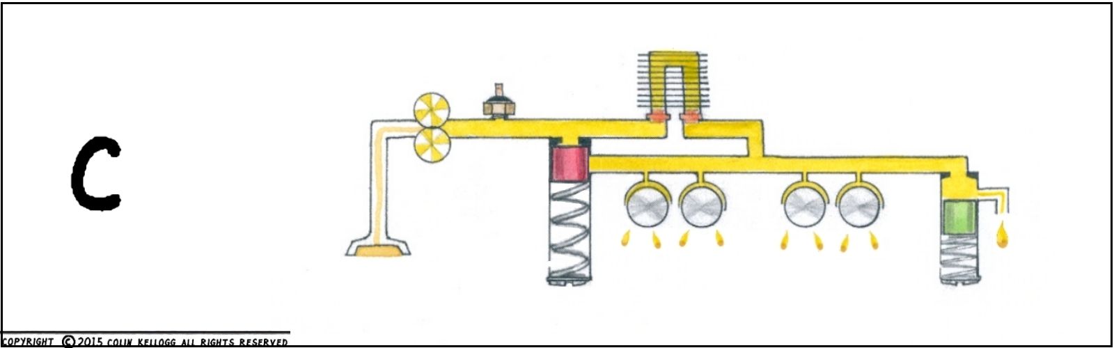
Introduced in the 1970 model year with a dished-in camshaft gear so the pump could fit, this design improvement expanded upon that trick "waste circulation" in a whole new way. With a super pump and a newly dedicated "control" dump valve at the other end of the main gallery, VW got rid of the grooved relief valve piston to allow total switch-off of waste circulation when the pressure dropped.
(note that the Muir book and others erred when they did not list that the control valve was introduced simultaneously with the super pump. Indeed, a 26mm pump was introduced the very next year in 1971, but that was a "very incremential" bump-up to help maintain FLOW through the new doghouse oil cooler adapter)
Now we have cold engines that can:
a) get rid of excess cold oil volume-thus-pressure,
b) allow even more waste oil circulation through the cooler than the engine actually consumes, and the control valve can close off the waste circulation! yay! at the first sign of hot/worn engine pressure drop when the bearings expand due to heat/age.
This illustration shows a fresh warm engine with its "about 16.0 pounds of spring pressure" closed relief valve (so the oil cooler can cool all of the oil), but at the same time, the "about 8.5 pounds of spring pressure" control valve is bleeding off the excess capacity oil volume from the 24mm pump because it still has nice .002" bearing clearances.
Similar to HVAC heating and cooling thermostats, this new control valve has a "cut-in and "cut-out" differential to prevent too much cycling. This valve works in tandem with the relief valve to bias flow through the cooler. Get your spring pressures right!
As per jimmy111's excellent February 17, 2008 write-up on theSamba,
Dual Relief Oiling System. How it works.
http://www.thesamba.com/vw/forum/viewto ... 80ae8b1ffc
the small closed-valve surface area exposed to the gallery means that it opens at about 50-60 psi, a good pressure to open at, but once pushed down, the full surface area of the piston is exposed to gallery pressure . . . it will not close again until the pressure drops to about 28 psi. This roughly "brackets" the system operating pressure specifications of 28-42 psi. It also insures that dedicated oil cooler flow is maintained with a warm engine, because the relief valve needs to close ahead of the control valve. If you want to screw with the spring pressure or botch the seat profiles here, be prepared for the *relief* valve to wear prematurely in its bore as it becomes the oil equivalent of the little red UniSyn carb airflow indicator forever bobbing in its bore to the vagaries of engine rpm.
ILLUSTRATION D
But What About? . . . ex. 1
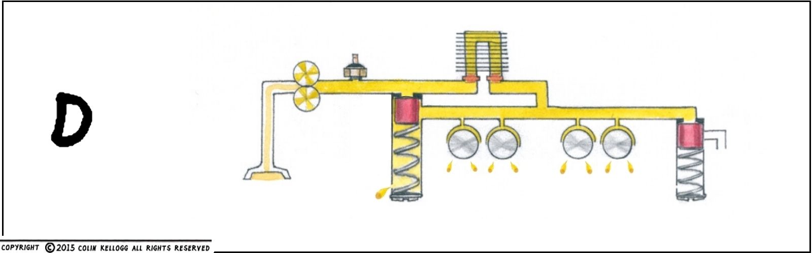
But what about a leaky pressure relief piston? Not a big deal, say I. With a healthy engine, there is plenty of excess capacity to allow gallery oil to leak between the wall of the piston and the bore. It will act somewhat like a "grooved 1500 pressure relief piston." That is all.
ILLUSTRATION E
But What About If It Is Worse Than That? ... ex. 2
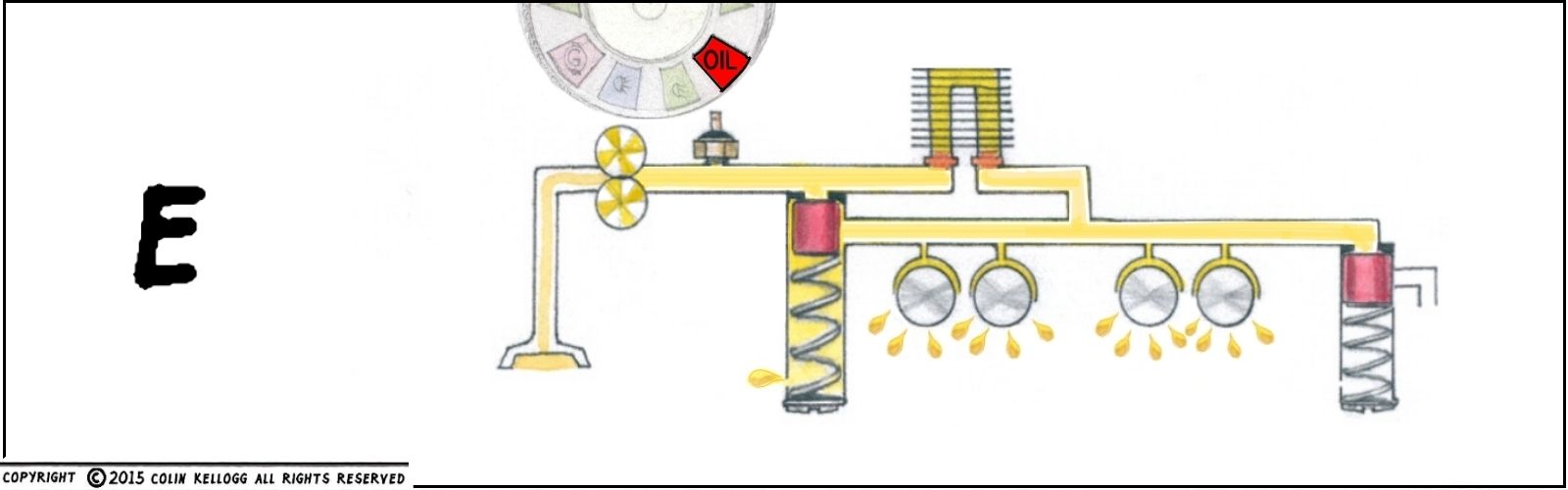
But what about a leaky pressure relief piston in an older engine? See all of those oil drips cascading out from the bearings in the illustration? They reflect what was written further up. Worn bearings (at the factory wear limit) consume up to *25 times the volume* that fresh bearings do. Oil leaking from the main gallery to the dump port at the relief valve does not change the fact it still opens when pressure is (thankfully) high enough, and it still closes when pressure drops. However much the system pressure may further drop cannot be addressed by a stronger spring pressing against an already closed! relief piston dribbling oil from the gallery to the dump port and vent hole. The quantity of oil that is able to flow past the piston wall and the relief bore wall is substantially less than the leak of worn bearings.
(p.s. just did an experiment on my 1970 dual relief engine -
a) no spring in relief bore yielded no change in oil pressure, as piston at the bottom of the bore blocked the vent hole
b) removed piston entirely and had no oil pressure at idle, light would go out at 2,000 rpm )
ILLUSTRATION F
Type 4 Engine Hey It Has A 24mm Pump Operating Temperature
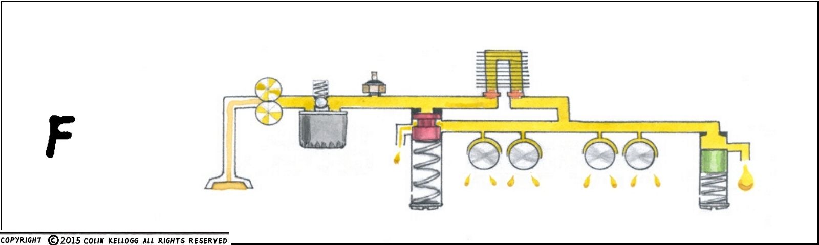
The Type 4 engine re-utilizes the grooved relief valve plunger bleeding off excess volume and has a control valve located along the right lifter gallery between #1 lifter bores and it has massive bearing surface area . . . and a modest 24mm pump, even with the new oil filter. Did I mention that increased bearing area reduces the need for bucketloads of oil? I just did. But what about the 85 hp Porsche 914 shifting at 5,799 rpm? Yeah, same difference.
This illustration is of a typical happy Type 4 engine running down the road with "about 17 pounds spring pressure" having already closed the relief valve to make sure that the oil cooler has a dedicated oil flow from pump to the bearings and the "about 4 pounds spring pressure" control valve dump is still open, and the grooved-yet-again relief piston is bypassing some oil to the relief bore's dump.
[ we once again interrupt this broadcast to announce the following Type 4 Oil Filter Bypass bulletin:
There is another relief valve inside the oil filter mount that opens at only 9-12 psi.This does not mean that it opens every time there is more than 9 psi oil pressure in the engine. A well-maintained filter can flow 4 gpm of factory specified viscosity at 34*, that is what your positive displacement pump flows at 3,500 rpm dead cold, so don't . . . do that. Only if/when the filter cannot maintain a *flow rate* that is within a 9-12 psi differential between the filter's own "in" and "out" will the relief open. This occurs only very briefly when the engine is cold and the galleries haven't yet blubked up to full cold pressure, and during hot low viscosity high speed operation when you haven't changed your filter since forever and you deserve to die anyway. As George Nehls, P.E. wrote of a conversation between Gary Cross of Melling Automotive who communicated in a phone call with Gary Bilski of Allied Signal who punched out the numbers on his calculator, "something between one ten thousandth and one one hundred thousandth of the total oil flow in sixty hours of operation bypasses the oil filter." Type 1 engines have been running around for over sixty years without even possessing an oil filter , so, like, don't worry about it? ]
ILLUSTRATION G
Older Type 4 Engine
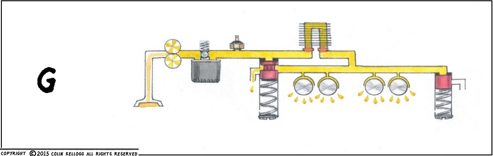
A warm older engine is depicted here by the cascade of little drips pouring off the clattery bearings. The control valve is hardly ever asked to bypass any more in the warm engine now that it is in its dotage. There is some bypassing going on at the relief valve main gallery port-to-dump groove, but lower system pressure means that the relief spring can easily keep the piston closed so all the oil is at least run through the cooler for "viscosity enhancement".
So here is a question:
What on Earth does a heavier spring at the relief or control valve do for low operating oil pressure?
Answer: Nothing.
With factory correct spring tensions, those valves are shut below let's say 28 psi . . . and they will not push open until 60 psi where your engine may not be able to go anymore anyway.
Do you think that heavy springs make them more shut? Really really shut? If you have low oil pressure, *the springs are out of the loop*.
ILLUSTRATION H
Tired Old Type 4
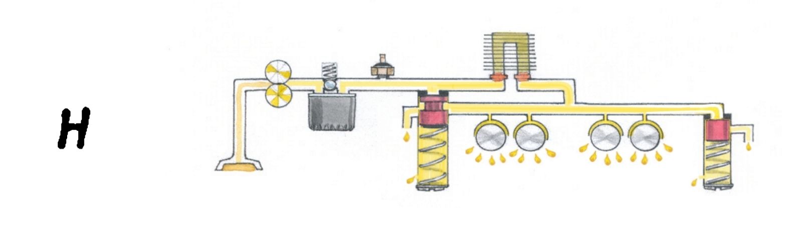
Here is a Type 4 engine with loose bearing clearances, loose relief piston, and even a loose control piston. All components are exactly where they belong, pistons are seated, slop between piston walls and bores only allow some oil flow and the vent holes only allow so much to pass at the bottom of the bores. The relief valve dump is doing pretty much what it has been doing since the engine was new, the control valve dump only passes what can escape between the piston wall and the bore. The primary cause of low oil pressure at idle is the leak rate past the bearings. When you read "bearings", remember that we are talking about 11 rapidly spinning journals, 8 lifters, 8 rocker arm bushings, all capable of passing 25 times the volume they used to.
[we interrupt this program for the following Type 4 Control Valve bulletin . . .
Type 4 control valves were NOT used in hydraulic lifter engines for the simple reason that the lifters happily utilized cold oil pressure to pump themselves up if and as necessary. Hydraulic lifters are continually bleeding themselves in operation at every down ramp off the cam lobes. I speculate that if you revert to solid lifters in a hydraulic non-control valve crankcase, the relief valve might spend too much time towards the bottom of its bore, playing "high rpm control valve", diverting oil that should be making a dedicated loop through the oil cooler ]
ILLUSTRATION I
A Modified Relief Valve In What Would Be The Warm Operating Or Shut Off Position But . . .
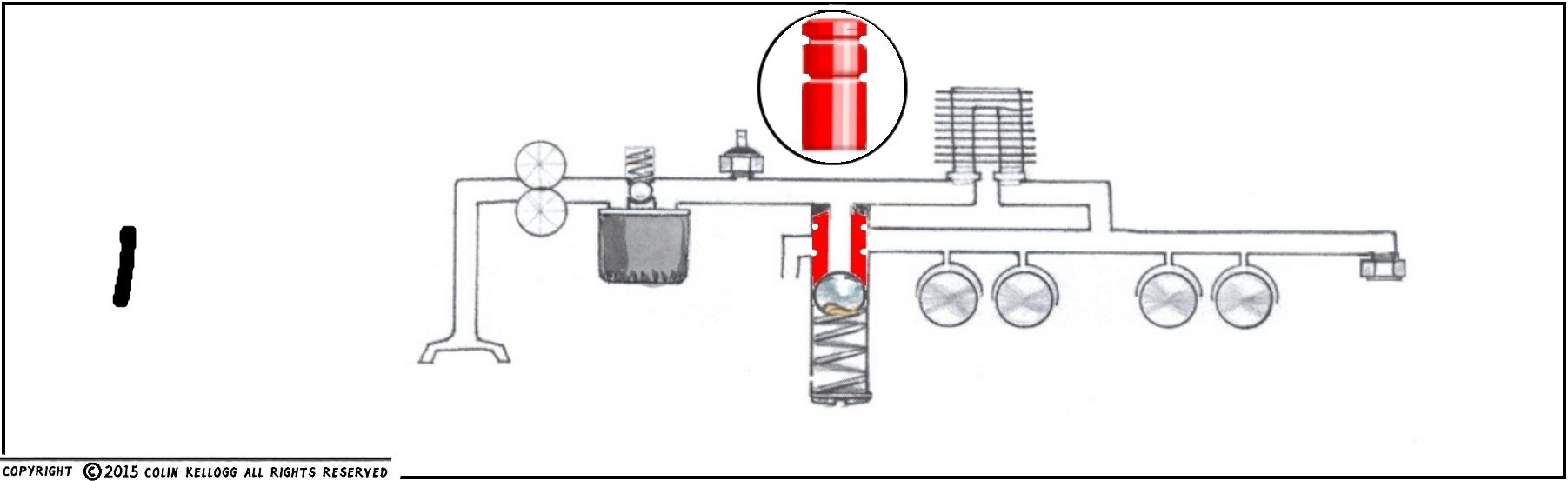
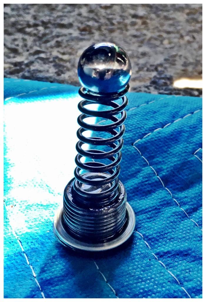
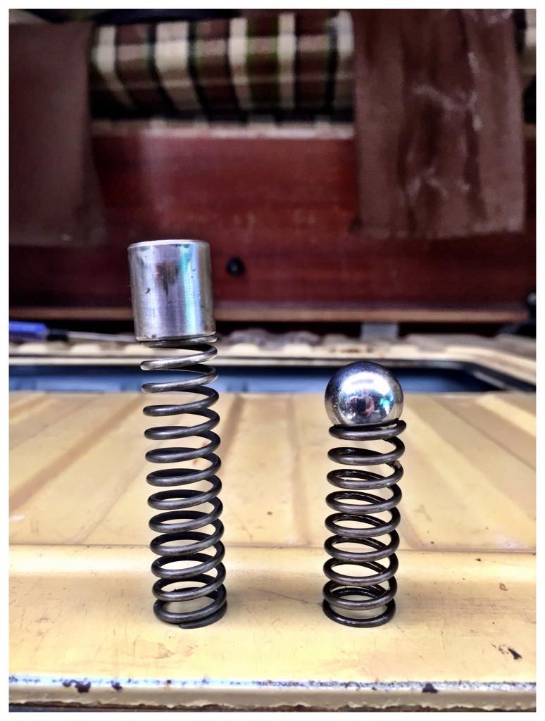
On February 14, 2015, a customer and I had a substantial oil leak located just above the relief valve bore, seconds after starting a rebuilt 2.0 engine for the first time. The leak was coming out from a threaded steel gallery plug that looked to cap the dump bore drilling. As we were trying to figure out this leak, it spontaneously ceased as the engine warmed up to the 5- 10 minute point. That suggested having a look at the relief valve. I loosened the big slotted screw, keeping it pressed against the threads (you know what 19 lbs of relief valve spring pressure can do to soft aluminum threads on their last tur. . . never mind. There was *no* spring tension. I would have to assume that this is an error. A truncated grindedidy-offed half spring slid out. Then a BALL fell out.
ILLUSTRATION J
Modified Relief Valve Under Cold/High RPM
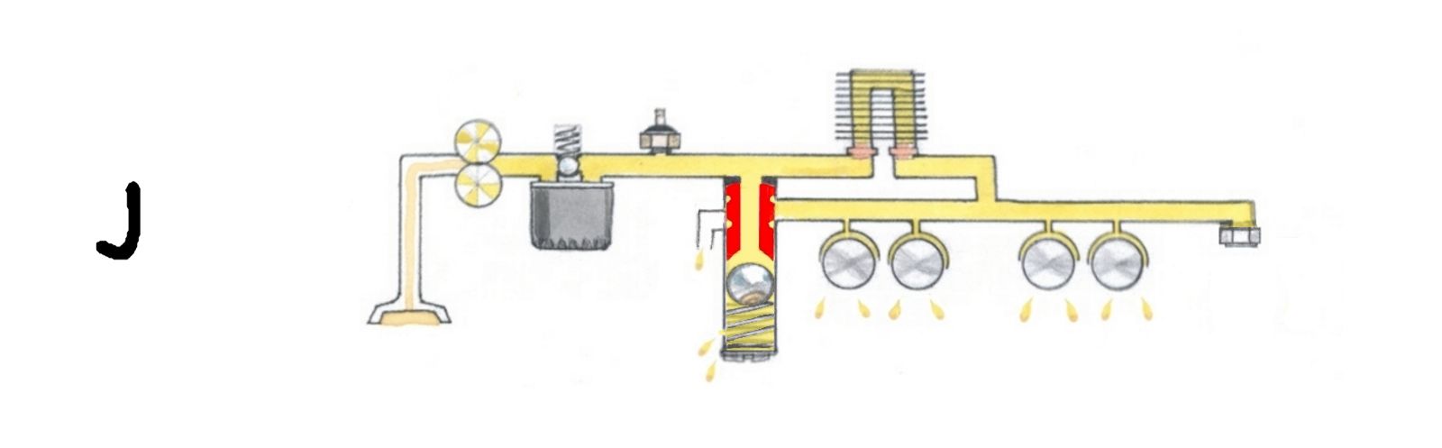
I cannot figure this one out. I see a substantial bypass capability when the ball is pushed down, which is helpful but I wasn't able to see how the ball could "switch" the pump path to the main gallery when cold.
DISCUSSION
Because the air-cooled VW engine oil temperature and pressure control system utilizes viscosity and pressure in a precisely calibrated manner, you can be very sure that things change in a hurry if you start goofing with the hard-engineered pump capacity, spring tension/piston seating in relief or control valve, or oil viscosity.
Pick one of the below threshholds.
Your relief valve can't tell the difference between:
a) big 30mm pump = 220* oil due to late switchover to cooler
(note that at this instant, the oil is exactly the same pressure as below, but is hotter)
b) factory pump = 180* oil due to on-time switchover
c) monster relief spring = early switchover to cooler, but no difference to old or hot engine oil pressure
d) low viscosity 5w30 oil= early switchover to cooler and lower old or hot engine oil pressure
e)monster control spring > risk of cold oil cooler/gallery plug damage, excessive and unwanted relief valve action, not a lick of help to old or hot engine idle pressure
If you have low oil pressure at the specified rpm and viscosity, you have an imbalance between pump output and bearing leak-out. Many online vendors suggest installing a higher capacity pump or "heavy duty relief springs", primarily because they are selling higher capacity pumps and heavy duty relief springs. Heavier relief springs can blow up coolers by preventing the dump port from limiting cold system pressure, but you are still in your world of hurt at high temperatures.
High capacity pumps can just totally overwhelm the cooler and dump ports of both relief and control valves at cold temperatures, and they might serve as temporary bandaids while your engine suffers, I bring you that poor Vanagon 2.1 with the ovalized connecting rod that tried to warn the owner with diminishing oil pressure at highway speed. The new pump kept that warning buzzer off even when the #4 rod went through the case.
The most overlooked critical component to a healthy lubrication system is correct bearing clearances.
How many of us are building our engines with bearing clearances at the low end of the specification window? Are we instead just hitting somewhere in the range?
If factory main bearing clearance specifications call for .002" to .005" (wear limit .006"),
how many of our engines are coming in at .004"- .005", "good enough! It says SO right THERE" ?
If the factory is looking for .0008" to .0027" at the connecting rods, how many of us are landing at .003", "aw heck get off my back, this ain't no Raby engine . . ."
Are we nailing our camshaft clearances with these bearings from Brazil? Our engines require an eye-opening attention-getting .0008" to .002" (wear limit .0047") clearance, I'd aim for .001" to .0015" and make sure I washed my hands too.
Type 4 carbed engine cases that no longer have a fuel pump installed, need to be checked for a gaping fuel pump pushrod hole that intersects the right lifter gallery. If it has not been sleeved, well, you will be amazed at how much oil pressure you can not-have in an otherwise tight engine.
Some of us are 1/2 to 3/4 of the way through the expected service life of our fresh rebuild before it even leaves the bench. Look at those (shocking, I tell ya) oil consumption rates again. Right there, under the beautiful paint and new exhaust system and anticipatory hopefulness, we might have an engine that is relegated to maybe 50,000 miles saddled with questions about low oil pressure, while someone else gets 135,000 miles with an idiot light that has never come on at brutally hot temperatures AND a low idle.
I personally aim for .002" or .0025" on main bearings (#2 main slightly tighter, look at the Bentley), I shoot for a maximum end play of .003" at first start.
The connecting rods, well, .001" would be lovely, but because I have yet to work with a machinist who can vouch for the accuracy required for the factory-blessed .0008", I am a scairdycat .002". I did reassemble a Raby kit that had every connecting rods at a deadnuts accurate .0008" (unbelievable!), but it was unfortunately assembled by someone without proper regard for the very needed exquisite cleanliness, and those poor rods were initially bound to the crankshaft by contamination. When my customer and I were done, they slowly slowly glided down like a hydraulic strut-equipped Lexus glovebox door.
(p.s. tight bearing clearances do create extra heat, but the heat graph shows that you're cool enough at .0015" so while you are breaking in your .002" engine, just take it easy for 1,000 miles, you can spin er up briefly and frequently after the first 100 miles of course, but don't cruise at 4,000 rpm until everything is polished and friction-free)
That is the crux of it. Building an engine with serious loyalty to the exacting German engineer's specificity will erase many of the issues we contend with and then chase down numerous dead-end alleys. It demands that we "blueprint" and dot every "i" and cross every "t". If your bearing clearances check in sucky sloppy during your build up, bite the bullet and turn down the journals to the next undersize, but be prepared to pay attention through the entire process. You need your new undersize bearings beautifully and cleanly installed and torqued down, then measured accurately, then you have to somehow convince your machinist to come in at the high end of the specified undersize diameter (low end of the clearance) and polish to the best-accepted microfinish for your bearings with the "fuzz" opposite to the operating rotation (10 rs?), it goes on and on, but it is fun. Is there anyone left who will go the last mile with you?
Look at how that old 1971 vintage 26mm oil pump was stuck on every Type 1/3 engine and watercooled Vanagon from the factory up to 1991, the 24mm Type 4 pump handled Porsche 914s to 5,800 rpm, these pumps worked fine for decades within factory tolerances right through to the end of the engines' service lives, and you bet they did communicate through low pressure that it was time for a rebuild, but who was listening? We just kept driving, "what's that noise?", didn't we? At the next rebuild, the "only available" camshaft bearings had .004" clearance out of the box, the undersized connecting rod journals had to be cut a little extra low to clean up that deep groove, you know? and the #1 main bearing was loose in the crankcase bore, the new!-cuz-you-NEED-it! Shadek Leak-O-Matic oil pump washed out the Permatex between the case and the pump body, and sure, oil pressure becomes a problem when every galled rocker shaft has a bobbling rocker arm, but the rebuilder needed to get the work going out the door, "did I put a new o ring on that oil pick-up?" "oh, don't worry about that oil light at idle, the engine is just running a little hot during break-in."
I have been unbelievably blessed with a lifetime of no lubrication problems with my stock engines in 30 years, I did blow a gallery plug at 417,000 miles on the Road Warrior, but that was for other reasons)
I like the factory lubrication systems. They have never let me down.
Colin


